Integration Model Editor: Difference between revisions
Created page with "The Integration Model (IM) Editor is a groundbreaking new region of PHENOM that combines visualizations with direct model editing. The Integration Model is perhaps the most important model of them all. It provides a representation of how your UoPs and communication channels are laid out in the physical world. A well-designed IM is what allows us to generate a fully configured CinC transport layer. == UoP Instances == '''UoP Instances''' are, as the name suggests, inst..." |
m Added images to imeditor page |
||
| Line 9: | Line 9: | ||
Each one is given a name and a Configuration URI. You are also expected to select some subset of the UoP's Connections to use as '''Endpoints''' in the '''UoP Instance'''. | Each one is given a name and a Configuration URI. You are also expected to select some subset of the UoP's Connections to use as '''Endpoints''' in the '''UoP Instance'''. | ||
[[File:Imeditor - UoPInstance.png|none|thumb|920x920px]] | |||
== Transport Channels == | == Transport Channels == | ||
| Line 28: | Line 27: | ||
=== Transport Nodes === | === Transport Nodes === | ||
Transport nodes come in several flavors which can be created by dragging and dropping from the Stencil tool on the left-hand side. | Transport nodes come in several flavors which can be created by dragging and dropping from the Stencil tool on the left-hand side. | ||
[[File:Imeditor - TransportNodes.png|none|thumb|916x916px]] | |||
Once placed in the '''Context''', the Node Inspector on the right-hand side is used to give the nodes names, descriptions, and other data specific to its type. | Once placed in the '''Context''', the Node Inspector on the right-hand side is used to give the nodes names, descriptions, and other data specific to its type. | ||
[[File:Imeditor - Sidepanel.png|none|thumb|916x916px]] | |||
*'''Sources''' / '''Sinks''' have only one port. These represent elements that simply produce or consume Views. | *'''Sources''' / '''Sinks''' have only one port. These represent elements that simply produce or consume Views. | ||
* '''Transforms''' consume one type of View and produce another. The Node Inspector is used to adjust settings. Notably, the Transform type is used to change from A) an Automatic transform that draws on semantic and measurement information to mediate between the two Views: | * '''Transforms''' consume one type of View and produce another. The Node Inspector is used to adjust settings. Notably, the Transform type is used to change from A) an Automatic transform that draws on semantic and measurement information to mediate between the two Views: | ||
[[File:Imeditor - AutoTransform.png|none|thumb|221x221px]] | |||
, and B) manual transform, which allows arbitrary assignment fields which will be parsed and incorporated into the generated transformation code: | , and B) manual transform, which allows arbitrary assignment fields which will be parsed and incorporated into the generated transformation code: | ||
[[File:Imeditor - ManualTransform.png|none|thumb|282x282px]] | |||
* '''Filters''' require a 'Test' field that will filter out Views for which the test evaluates to False. | * '''Filters''' require a 'Test' field that will filter out Views for which the test evaluates to False. | ||
| Line 52: | Line 46: | ||
=== Connections === | === Connections === | ||
Connections are created by dragging from an output port to an input port: | Connections are created by dragging from an output port to an input port: | ||
[[File:Imeditor - Connection1.png|none|thumb|722x722px]] | |||
If the data types are inconsistent then the connection will turn red and you won't be allowed to save. In this situation, we have a Transform node outputting ComplexTypes, and sending it to an Endpoint expecting BasicTypes: | If the data types are inconsistent then the connection will turn red and you won't be allowed to save. In this situation, we have a Transform node outputting ComplexTypes, and sending it to an Endpoint expecting BasicTypes: | ||
== Code Generation == | == Code Generation == | ||
CinC generation targets a different type of element called a '''Main Program'''. These are created from the main 'CREATE' dropdown. | CinC generation targets a different type of element called a '''Main Program'''. These are created from the main 'CREATE' dropdown. | ||
[[File:Imeditor - Codegen1.png|none|thumb|830x830px]] | |||
Once your Main Program exists, you can associate UoP Instances to it so they become part of the generated code. | Once your Main Program exists, you can associate UoP Instances to it so they become part of the generated code. | ||
[[File:Imeditor - Codegen2.png|none|thumb|834x834px]] | |||
Similarly, Main Programs can be placed in '''Processing Elements''' - but these are not incorporated into generation yet. | Similarly, Main Programs can be placed in '''Processing Elements''' - but these are not incorporated into generation yet. | ||
Revision as of 15:41, 19 July 2024
The Integration Model (IM) Editor is a groundbreaking new region of PHENOM that combines visualizations with direct model editing.
The Integration Model is perhaps the most important model of them all. It provides a representation of how your UoPs and communication channels are laid out in the physical world.
A well-designed IM is what allows us to generate a fully configured CinC transport layer.
UoP Instances
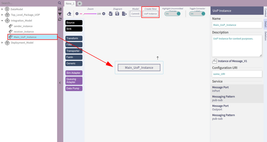
UoP Instances are, as the name suggests, instantiated Units of Portability. They can be created from the IM Editor or from the 'Create' dropdown in regular Navigate mode.
Each one is given a name and a Configuration URI. You are also expected to select some subset of the UoP's Connections to use as Endpoints in the UoP Instance.
Transport Channels
A Transport Channel holds information required to transmit across some outside channel.
Currently UDP channels are supported.
At the moment, you are expected to use the description field to populate the following comma-seperated values: ip, local port, destination ip, destination port, ttl.
Integration Contexts
This is where we find the real meat and potatoes of your integration situation. A Context is a graph representing the flow of DataTypes, or Views, amongst UoP Instances.
A given context can pull in the items discussed above. In fact, a given UoP Instance might be used in multiple Contexts. The different Contexts simply illustrate different aspects of the layout.
The IM Editor lets you work on one Context at a time. First, drag and drop to insert a UoP Instance. (Technically, the UoP Instance exists outside the Context, but since it's connected to things inside, it will be useful to have it here).
Transport Nodes
Transport nodes come in several flavors which can be created by dragging and dropping from the Stencil tool on the left-hand side.
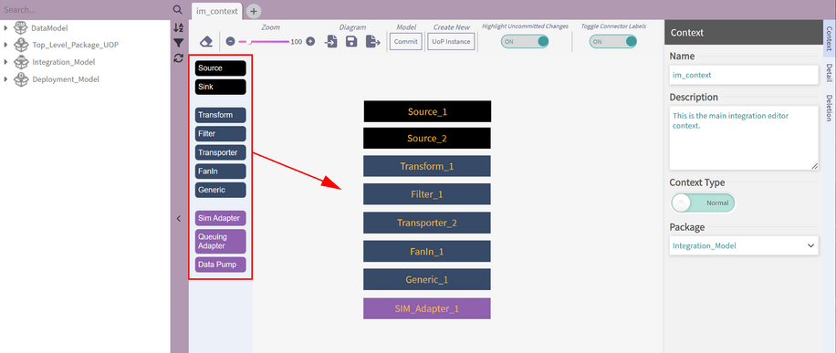
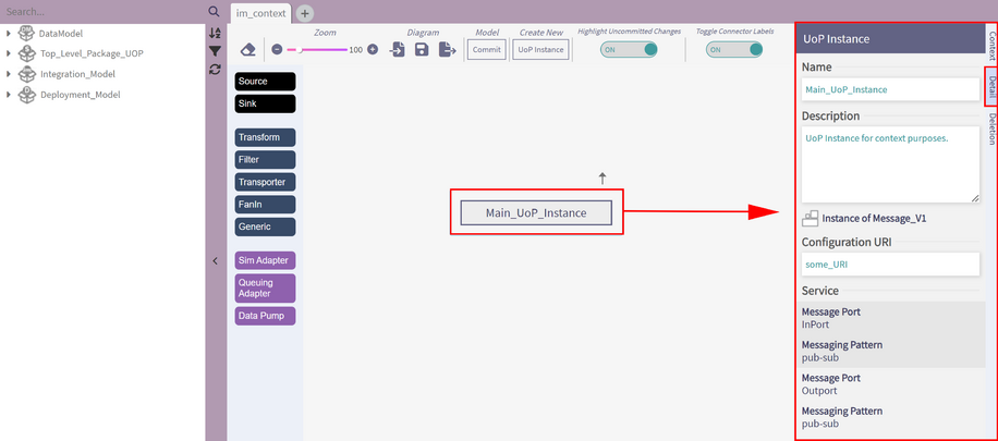
Once placed in the Context, the Node Inspector on the right-hand side is used to give the nodes names, descriptions, and other data specific to its type.
- Sources / Sinks have only one port. These represent elements that simply produce or consume Views.
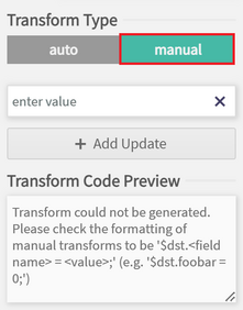
- Transforms consume one type of View and produce another. The Node Inspector is used to adjust settings. Notably, the Transform type is used to change from A) an Automatic transform that draws on semantic and measurement information to mediate between the two Views:
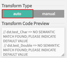
, and B) manual transform, which allows arbitrary assignment fields which will be parsed and incorporated into the generated transformation code:
- Filters require a 'Test' field that will filter out Views for which the test evaluates to False.
- Transporters allow you to select a Transport Channel to transmit across.
- Data Pumps periodically poll the previous block to move messages forward.
The Adapter blocks allow interoperability when the UoP Message Port is expecting a certain kind of communication style.
- SIMAdapters for Single Instance Messaging communication style.
- QueuingAdapters for Queuing communication style.
Connections
Connections are created by dragging from an output port to an input port:
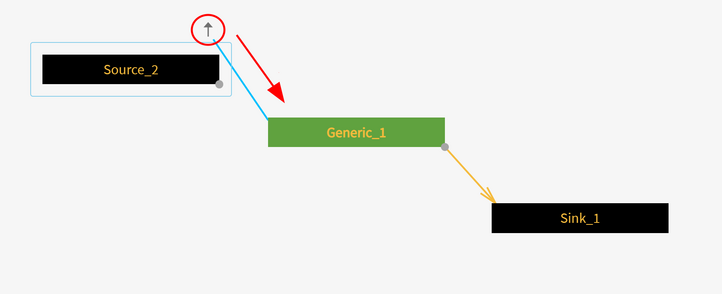
If the data types are inconsistent then the connection will turn red and you won't be allowed to save. In this situation, we have a Transform node outputting ComplexTypes, and sending it to an Endpoint expecting BasicTypes:
Code Generation
CinC generation targets a different type of element called a Main Program. These are created from the main 'CREATE' dropdown.
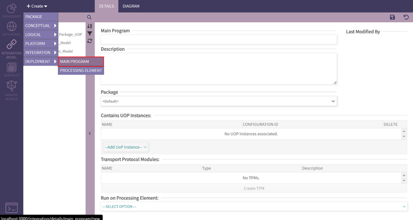
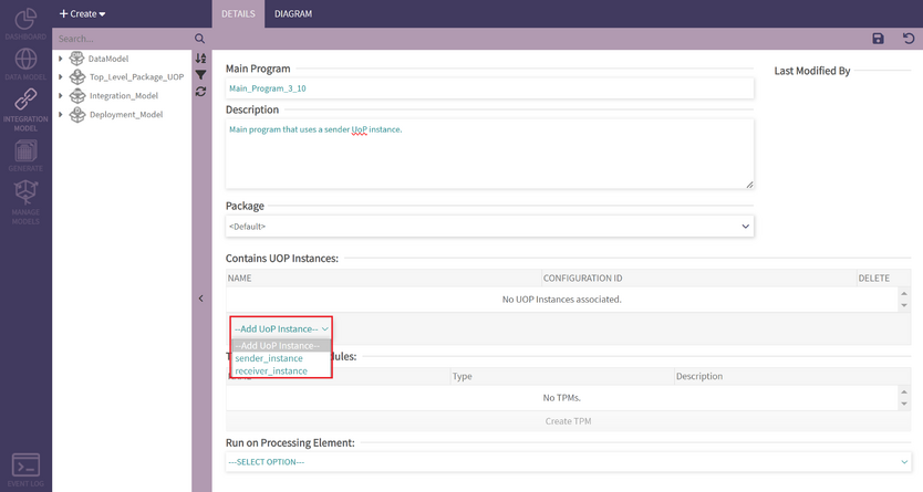
Once your Main Program exists, you can associate UoP Instances to it so they become part of the generated code.
Similarly, Main Programs can be placed in Processing Elements - but these are not incorporated into generation yet.