Document Interfaces using PHENOM Portal
Documenting communication interfaces using good data modeling practices is easy in PHENOM Portal. This quick assignment will get you up and running documenting your own interfaces, creating valid and informative paths, and mapping your interface to others already documented.
Preparing PHENOM
In this tutorial, you will be documenting interfaces. However, in order for you to be able to do this, you need a data model that corresponds with this tutorial. Since there is already a tutorial for Developing an Entity Model, this tutorial will start by loading a data model into PHENOM.
Start by downloading this data model: File:Robot model.face
Switch to Manage Mode
All model management functions are performed in the Manage Models section of PHENOM. After logging in, please click on the Manage Models icon.

Create a New Project
It is possible to upload new content and create a new project all at once! To start, click on the Create New Project button.

Two Buttons? If you have a project selected, a second button will appear. This is for Create Filtered Project which will be covered in another article.
|
Select Models
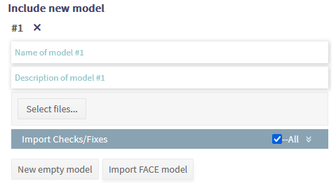
Once you click the button, the following screen should appear to the right of the Project listing.

For the Project Name, please type: Robot
You may leave Description blank. This field is intended for you to capture notes about the project (or model) and how it will be used.
In the bottom-left of this display, there is a list of existing models. This is used to add existing models to the new project. Ignore this for now.
In the bottom-right, click on Import FACE model. This button will add a model entry as follows:

For the Model Name (the first text field), please enter: Robot_model
As before, Description can be left blank.
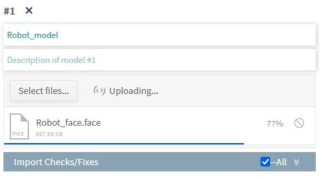
Click on Select files... and a file chooser will appear. Navigate to where you saved Robot_model.face from before and choose that file. PHENOM will immediately start uploading the file. While the file is uploading and being preprocessed, the following status will appear:

Once the file has successfully transferred, PHENOM will show the file uploaded successfully with a green indicator.

In the event of an error (e.g., invalid file type or invalid model), PHENOM will display an error as follows:

Once the file has been successfully uploaded, click on the SAVE button.

Switch to New Model
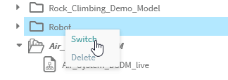
After saving the model, it will appear in the project browser. Simply right-click on Robot and choose Switch. This will load the new project and you are finally ready to start this tutorial!

You can verify that you have switched to the new project by looking at the top of your PHENOM display. The current project is displayed beside your username.

Prelude: Views, View-Characteristic, and Paths - What and Why
In the task of documenting the Simple Operating Robot Data Interface, our main focus will be in Views. Views can be understood as the documentation of messages that the interface describes. A view documents a message interface, and each view-characteristic documents a single field of the message. More specifically, a view-characteristic contains information about the logical level of the message field (such as the measurement and unit being used) as well as information about the conceptual level of the message field (which entities and properties of entities are being talked about).
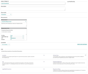
If you click on a view-characteristic, you will see that each has a name, an observable, a measurement and axis (which further characterizes the observable), and a path documenting the entities and its context. Path development is the primary focus of this assignment - paths communicate the semantics of message fields in a machine understandable fashion. Engineer-written documentation for data coming in over the wire might indicate "Temperature of the main unit of an air system's propulsion system." which, though concise and informative, might not mean much to a machine. Paths allow us to write standardized descriptions of view-attributes, linking together different entities, such as engines, propulsion systems, and air vehicles, to create semantic, machine-readable documentation for the contents of a message. Below is an example view attribute describing the message field documented in the sentence above.

Take a look at the path and see if you can connect it to the meaning intended by the engineer from the previous paragraph. Note that this page also captures how the measurement of this concept is expressed (i.e., measurement units and frame of reference). This information is used to construct the Logical Data Model.
Part 1: Documenting Robot Position Status
The first message interface we have to implement is for communicating the Robot_Position_Status - the message that returns position information of the robot. We are given the following interface description:
| Field ID | Name & Description | Unit | Data Type |
|---|---|---|---|
| 1 | Robot_IdAn alphanumeric string indicating the unique identifier of the robot system. | UTF-8 | String |
| 2 | Latitude The WGS-84 latitude value. | Radians | Double |
| 3 | LongitudeThe WGS-84 longitude value. | Radians | Double |
| 4 | AltitudeThe altitude value expressed in MSL. | Meters | Float |
